4.3.1. Defining nodes and elements by hand
Until now, only trivial meshes, e.g. the 1d LineMesh or the 2d RectangularQuadMesh have been considered. However, in reality, these will rarely be sufficient for all kinds of problems. There are essentially two ways of creating meshes in pyoomph. The first way is to add all elements by hand. This can be a demanding task, but gives full control over the desired mesh. This approach can also be used to write custom classes to load a mesh from a file in any format.
To do so, we write a mesh class that inherits from the MeshTemplate class. Let us create a mesh that resembles an \(L\)-shape:
from pyoomph import *
from pyoomph.equations.poisson import * # use the pre-defined Poisson equation


class LShapedMesh(MeshTemplate):
	def __init__(self,Nx=10,Ny=5,H=1,W=1,domain_name="domain"):
		super(LShapedMesh,self).__init__()
		self.Nx=Nx
		self.Ny=Ny
		self.H=H
		self.W=W
		self.domain_name=domain_name

	def define_geometry(self):
		domain=self.new_domain(self.domain_name)
		# row of quads in x direction
		for ix in range(self.Nx):
			x_l,x_u=self.W*ix,self.W*(ix+1) # lower and upper x coordinate
			y_l, y_u = 0, self.H # lower and upper y coordinate
			# add the corner nodes. These will be unique, i.e. no additional node will be added if it is already present
			node_ll=self.add_node_unique(x_l,y_l)
			node_ul = self.add_node_unique(x_u, y_l)
			node_lu = self.add_node_unique(x_l, y_u)
			node_uu = self.add_node_unique(x_u, y_u)
			# add a quadrilateral element from (x_l,y_l) to (x_u,y_u)
			domain.add_quad_2d_C1(node_ll,node_ul,node_lu,node_uu)
			if ix==0: # Marking the left boundary:
				self.add_facet_to_boundary("left",[node_ll,node_lu])

		# row of quads in y direction
		for iy in range(1,self.Ny): # we must start from 1, since the element in the corner is already present
			x_l,x_u=self.W*(self.Nx-1),self.W*self.Nx # lower and upper x coordinate
			y_l, y_u = self.H*iy, self.H*(iy+1) # lower and upper y coordinate
			node_ll=self.add_node_unique(x_l,y_l)
			node_ul = self.add_node_unique(x_u, y_l)
			node_lu = self.add_node_unique(x_l, y_u)
			node_uu = self.add_node_unique(x_u, y_u)
			domain.add_quad_2d_C1(node_ll,node_ul,node_lu,node_uu)
			if iy == self.Ny-1: # Marking the top boundary:
				self.add_facet_to_boundary("top",[node_lu, node_uu])
Again, we pass arguments to the constructor, e.g. the number of elements Nx\(\times\)Ny in \(x\) and \(y\) direction. These are stored as properties of the class. The generation happens in the method define_geometry(). A MeshTemplate consists of nodes and elements. Nodes are part of the MeshTemplate itself, whereas elements are stored in domains. This will allow us to create multiple domains in the very same MeshTemplate, which is relevant for multi-domain problems in Section 7 later on. Therefore, before adding elements, we must create a domain to store these. This is done with the new_domain() method, which takes a name of this domain as argument. The name is arbitrary, but it is relevant to identify the domain. In particular, in the Problem class, we have to restrict the equations to the very same domain name, e.g. in the call add_equations(eqs@"domain").
The, we perform a loop over the \(x\)-direction. We calculate the corner \(x\) and \(y\) coordinates of each quad. Then, we add four nodes with the add_node_unique() call. During the loop over ix, a lot of nodes will be created multiple times. If the node is already present, add_node_unique() will notice that and return the already previously added node instead of creating a new one. Thereby, adjacent elements will indeed share the very same mutual nodes. Finally in the ix loop, we add elements to the domain. Here, we add first order quadrilateral elements with the method add_quad_2d_C1(). It takes the four corner nodes as arguments, where it is necessary to add them in a zigzag order, i.e. starting with one corner (e.g. lower left), move to the next corner (e.g. lower right), then go diagonally (e.g. upper left) and finally the last corner (e.g. upper right). It is furthermore important to add the nodes in the order that the corner points in the argument order \(1\), \(2\), \(4\), \(3\) form a counter-clockwise loop.
We do the same in \(y\)-direction. However, opposed to nodes, it is not checked whether elements were already added. Therefore, it is important that the \(y\)-loop starts with iy=1, not iy=0, to prevent the dual generation of the element in the corner of the L-shape.
Lastly, we also can add boundary markers. This is done with the add_facet_to_boundary() method, that takes first an interface name and then a list of nodes defining a single facet. This function must be called for each facet on the boundary. For higher order facets, a further argument, namely a list of vertex nodes is required as additional argument.
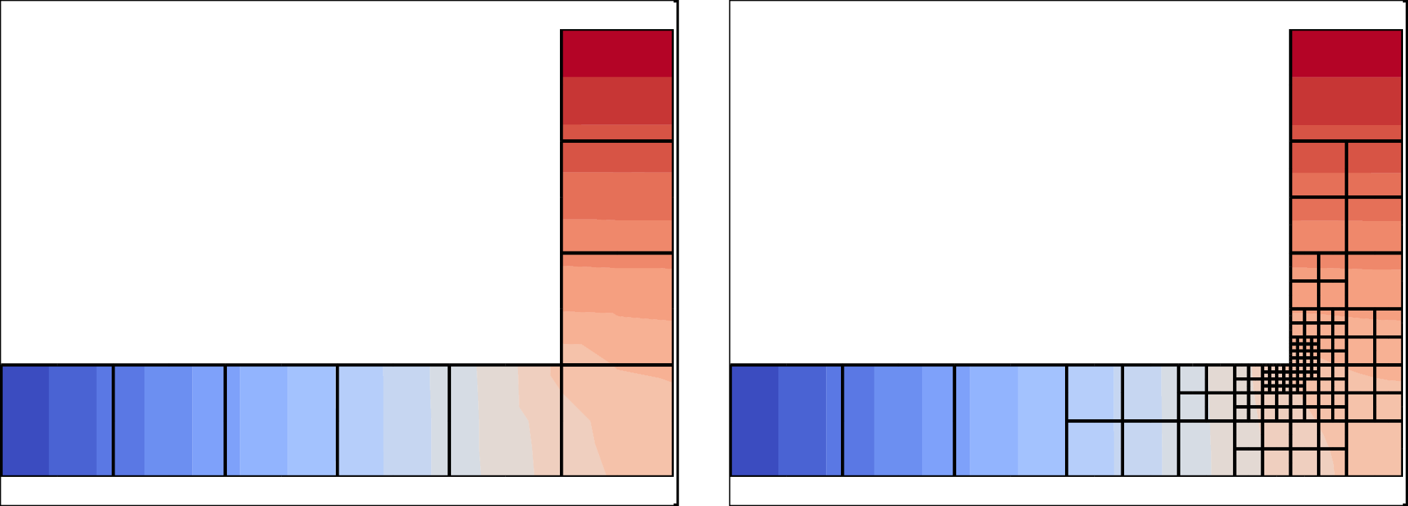
Fig. 4.12 Poisson equation on an L-shaped custom mesh without and with spatial adaptivity.
As an example how to use this mesh, we solve again a Poisson equation on this mesh, however, this time using the predefined PoissonEquation from the module pyoomph.equations.poisson:
class MeshTestProblem(Problem):
	def define_problem(self):
		self.add_mesh(LShapedMesh(Nx=6,Ny=4))
		eqs=MeshFileOutput()
		eqs+=PoissonEquation(name="u",source=0)
		eqs+=DirichletBC(u=0)@"left"
		eqs += DirichletBC(u=1) @ "top"
		eqs+=SpatialErrorEstimator(u=1)
		self.add_equations(eqs@"domain")

if __name__=="__main__":
	with MeshTestProblem() as problem:
		problem.initial_adaption_steps=0
		problem.solve(spatial_adapt=4)
		problem.output_at_increased_time()
The predefined PoissonEquation works as the one developed in Section 4.1. Note how we initially suppress the mesh adaption by setting initial_adaption_steps to zero. Otherwise, we would get redundant adaption near the "top" boundary due to the non-zero DirichletBC. The custom mesh and the problem class in action can be seen in Fig. 4.12.
Warning
The orientation of the elements can matter, in particular for refineable meshes. Therefore, it is advised to make sure that all elements are constructed by node indices in the same orientation. E.g. for a 2d mesh, the order of the nodes passed to add_quad_2d_C1() can either lead to an element facing in positive or negative \(z\)-direction. If elements of different orientation are connected in the very same mesh, this leads to issues upon spatial refinement. Therefore, make sure that all elements are oriented in the same direction by adjusting the order of the nodes passed to the construction of the elements. If it is wrong, pyoomph will raise an error, unless you set check_mesh_integrity of the Problem class to False. After doing so, you can easily check the mesh by Paraview. After outputting the mesh with MeshFileOutput, you can open it with Paraview and search for Backface Representation in the search box of the Properties box (hidden by default). Then, select Cull Frontface or Cull Backface. The entire mesh should be visible in one of these settings and entirely invisible in the other setting.